Protocol-level debug test

Serial bus protocol test

Whether USB or CAN Bus decoding confirming that data is being transmitted correctly between the modules connected to each other by serial bus, and that the data content is as intended, is a part of developing and maintaining any system using serial buses for data communication via a serial peripheral interface; over distances as small as a few millimeters for PCIe interconnects on computer boards, up to the 1700 meters possible with 10BASE-T1L Ethernet for factory automation,

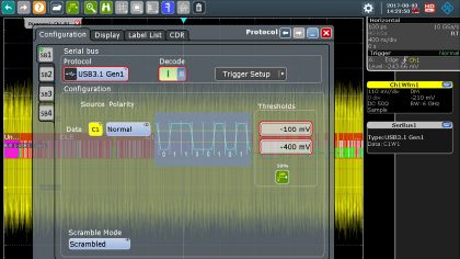
As the data communication is a series of events, oscilloscopes are best suited to investigating serial buses, primarily in the time domain. Both for debug and maintenance, two basic functions based on the protocol rules defined for a standard are required:

  • Trigger (and search) on protocol events
    The oscilloscope shall acquire the waveforms resulting from a selected bus event such as the start of a frame, frame ID, specified data content, or error conditions. Being able to use search functions to locate the part of the acquired waveform containing the trigger event quickly, greatly speeds any analysis.
  • Decode data
    Decode the binary values used to transmit data via a serial bus into a suitable protocol level for a man or machine to understand, such as alpha-numeric characters for plain text or hexadecimal values (for example) depending on the bus application.

Your serial bus protocol test challenges

You want to be confident that you have detected all the errors causing messages not to be transmitted correctly, and as quickly as possible.

You need to decode the message content to the suitable protocol level for analysis, whether this is machine-based or as a manual human task.

In bi-directional buses, you need to identify the direction in which a message is being transported.

Our serial bus protocol test solutions

The entire portfolio of Rohde & Schwarz oscilloscopes include serial bus trigger and decode software options, from the 50 MHz bandwidth 2-channel R&S®RTC1002 to the 16 MHz bandwidth 4-channel R&S®RTP. The protocols supported by each oscilloscope depend on whether its performance matches the individual protocol parameters such as bandwidth and data rate, and the amount of data to be decoded to make sense of its content and purpose.

The standards supported include;
I²C, SPI, UART, RS-232/422/485, 10BASE-T, 100BASE-T, MDIO, 8b10b, USB 1.0 – 3.1, USB-PB, USB-SSIC, PCIe Gen 1-3, CAN/LIN, CAN-FD, SENT, CXPI, 100BASE-T1 BroadRReach/Ethernet, 1000BASE-T1, MIL-STD-1553, ARINC 429, SpaceWire, MIPI RFFE, MIPI D-PHY v.1.2, MIPI M-PHY, Manchester, NRZ (configurable).

In many cases a test fixture is required to connect the device under test to the test instrument; Rohde & schwarz supply a wide range of test fixtures, including directional couplers to identify forward and reverse signals in full duplex standards.

As a test fixture has its own RF properties, these will affect the signal values measured. Rohde & Schwarz supply de-embedding functions to evaluate the impact of the test fixture on a test setup.

To sample a bus at locations throughout the device under test, Rohde & Schwarz supply all the necessary probes with a wide range of tips and other connectors, with high impedance and high bandwidth. The physical contact between a probe and the test point inevitably affects the electrical properties of the waveforms; Rohde & Schwarz supply functions to characterize and remove the influence of the probe from the measurements.

Related products

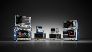
Oscilloscopes

更多信息

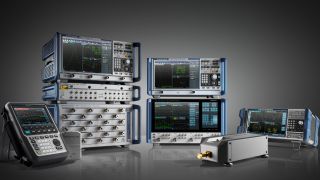
Vector network analyzers

更多信息

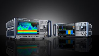
Signal & spectrum analyzers / Phase noise analyzers

更多信息

DC power supplies

更多信息

Your benefits from our serial bus protocol test solutions

Find what you are looking for quickly and easily with powerful Search functions on the protocol layer most suited to your needs; from signal properties to selectable levels of data content.

Detect even short transient disturbances and errors in need of debugging. The hardware-based high-speed acquisition and fast refresh rate minimizes the signal blind time.

Only invest in trigger and decode functions for serial busses in which you are interested. Add additional bus technologies as you require them quickly and easily.

The complete test setup including probes and test fixtures is from a single supplier.

If you have any further questions regarding serial bus protocol test solutions, please contact us.

Related content for serial bus protocol test solutions

Triggering and decoding Manchester and NRZ based buses

Supporting custom definition of bit coding and frame formats, the R&S®RTx-K50 option provides a powerful trigger and decode capability for standardized and proprietary Manchester or NRZ coded buses.

More information

Fast analysis of sporadic errors with segmented memory and history function

Analysis of an I2C signal with long communication pauses. Using both segmented memory and history function to record a signal and analyze the communication over a long time frame.

More information

Debug standard and proprietary serial buses in aerospace and avionic systems

The R&S®RTE and R&S®RTO oscilloscope families from Rohde & Schwarz provide in-depth tools for debugging custom and off-the-shelf serial buses for the avionics and aerospace industries.

More information

SPI bus decoding
SPI bus decoding

Decoding an SPI bus signal with an R&S®RTO oscilloscope and triggering on selected MOSI values.

Decoding for 100BASE-T1 Automotive Ethernet
Powerful 100BASE-T1 decoding

Decoding details for 100BASE-T1 Automotive Ethernet using an R&S®RTO oscilloscope with option K57.

Triggering for 100BASE-T1 Automotive Ethernet
Powerful 100BASE-T1 triggering

Triggering details for 100BASE-T1 Automotive Ethernet using an R&S®RTO oscilloscope with option K57.

Evaluating the performance of RF assemblies controlled by a MIPI-RFFE interface
Evaluating the performance of RF assemblies

This video demonstrates how an R&S®RTO oscilloscope option K40 can be used to measure response times of front end components such as power amplifiers and switches controlled by the MIPI RFFE control interface.

Serial bus decoding capability with an Oscilloscope
Serial bus decoding capability with an oscilloscope

Discover the powerful decoding capability of an R&S®RTO, decoding the protocol details in a CAN bus signal.

Related webinars

Efficiently triggering and decoding low-speed serial buses

This webinar addresses design and test engineers who are interested in crucial techniques to debug today‘s common serial buses with an oscilloscope. We will be discussing proper triggering, event isolation and tips for decoding and making advanced bus measurements. Solution demonstrations will reinforce the effectiveness and ease of use of the discussed techniques.

Register now

CAN bus debugging with an oscilloscope

This webinar explores the topic of debugging CAN bus interfaces by using an oscilloscope. We will be talking about topics such as sources of bus errors, EMI debug correlation with protocol decode, boot cycle testing, application specific triggering, eye measurements and more.

More information

Knowledge+

Experience the uniquely personalized, high-quality content from the whole Rohde & Schwarz ecosystem - all in a single place. Discover now our knowledge tailored for your needs.

Video center

Get access to interesting videos and webinars about solutions, applications and products.

More information

Download Center

Search the Rohde & Schwarz download center for brochures, datasheets, technical papers, manuals, firmware, software, drivers, and more.

More information

The Rohde & Schwarz Technology Academy

You’re in great hands
Practical knowledge. Industry insight. Real experts. Only with the Rohde & Schwarz Technology Academy.

More information

Sign up for our newsletter

Stay up to date on upcoming trends and latest applications.

Sign up for our newsletter

请求信息

如果您有任何疑问或需要了解更多信息,请填写此表格,我们会尽快回复您。

推广许可

你的申请已提交,我们稍后会联系您。
An error is occurred, please try it again later.